

okogawa Analog Input Module AAI143-S00
STANDARD SPECIFICATIONS of AAI143-S00
Current/Voltage Input Modules (Non-Isolated)
These modules provide 16 inputs of mainly 4 to 20 mA DC or 1 to 5 V DC standardized signals from 2-wire/4-wire transmitters.
They can be used in dual-redundant configuration.
Current Input Modules (Isolated)
AAI143 provides 16 inputs of 4 to 20 mA signal. It can be used in dual-redundant configuration.
| Items | Specifications |
| Model | AAI143 (*1) |
| Number of input channels | 16, isolated |
| Input signal | 4 to 20 mA |
| Allowable input current | 24 mA |
| Input resistance | Power ON 270 Ω (20 mA) to 350 Ω (4 mA) (*2) |
| Power OFF 500 kΩ or larger | |
| Accuracy | ±16 μA |
| Data update period | 10 ms |
| Transmitter power supply | 19.0 V or higher (at 20 mA) 25.5 V or less (at 0 mA) (output current limit: 25 mA) (*5) |
| Setting of 2-wire or 4-wire transmitter | For each channel by setting pin |
| Drift due to ambient temperature change | ±16 μA/10 C |
| Maximum current consumption | 230 mA (5 V DC), 540 mA (24 V DC) |
| Weight | 0.3 kg |
| External communication | Pressure clamp terminal, MIL connector cable, dedicated cable (KS1) |
| HART communication (*3) | Available |
*1: A Zener barrier is not allowed to be connected with this module. Use an isolation barrier when the module is used in
intrinsically safe application.
*2: The module input resistance viewed from the terminals depends on the current strength as calculated as below:
250 Ω +
current value
voltage drop in the input protection circuit
F04E.ai
*3: When this module is installed to a ER bus node unit with HART function, the EB401 firmware must be rev. 2 or later.
*4: When the dedicated cable is used, the withstanding voltage is 500 V AC (between the input signal and the system). When
the ML connector cable is used, the withstanding voltage depends on the electrical specifications of the cable.
*5: This voltage is generated between the connecting terminals for 2-wire transmitters for this module. When calculating the
minimum operating voltage for transmitters, consider to allow margins for voltage drop in external wiring.
Yokogawa Analog Input Module AAI143-S00
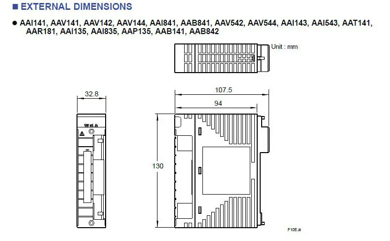
EXTERNAL DIMENSIONS of AAI143-S00
Yokogawa Analog Input Module AAI143-S00
MODEL AND SUFFIX CODES AAI143-S00
| Description | ||
| Model | AAI143 | Analog Input Module (4 to 20 mA, 16-channel, Isolated) |
| -S | Standard Type | |
| -H | With digital communication (HART protocol) | |
|
Suffix Codes |
5 | With no explosion protection |
| E | With explosion protection | |
| 0 | Basic type | |
| 3 | With ISA Standard G3 option and temperature (-20 to 70 °C) option | |
|
Option Codes |
/K4A00 | With KS Cable Interface Adapter [Model : ATK4A-00] |
| /A4S00 | With Pressure Clamp Terminal Block for Analog [Model : ATA4S-00] | |
| /A4S10 | With Pressure Clamp Terminal Block for Analog (surge absorber) [Model : ATA4S-10] | |
| /A4D00 | With Dual Pressure Clamp Terminal Block for Analog [Model : ATA4D-00] | |
| /A4D10 | With Dual Pressure Clamp Terminal Block for Analog (surge absorber) [Model : ATA4D-10] | |
| /CCC01 | With Connector Cover for MIL Cable [Model : ACCC01] |
Yokogawa Analog Input Module AAI143-S00
